Building a Sawmill
based off the Bill Rake ‘Simple Saw design’. March –
April 2014…
Video of our Version of the Simple Saw in use: Sawing Red oak
My son asked me if
we, ala I, could build a sawmill because he had access to lots of
standing timber and he saw it as a good hobby. He initially purchased
some plans from the internet for a chainsaw based system. But in
looking over the plans, the cost for the long – long chainsaw bar,
plus a very large chainsaw engine, plus special ‘ripping’ chains
kind of put the cost of doing that out of reach.
I recalled seeing
something about DIY bandsaw based sawmills. After some research I
found several free copies of plans, that are not of really high
quality, but they were enough to get me started, since I NEVER follow
anyone’s plans exactly anyway.
Photos of other peoples builds for more ideas: http://kruppt.tripod.com/mill_1/
The basic parts of
the Bandsaw mill are a lawnmower engine, I used a vertical shaft 12
HP Briggs since I already had it, 2 – 12 inch ‘boat trailer’
wheels on rims. Trailer hubs, shafts, belts and pulleys to drive
everything. Angle Iron for a track that in our case is sitting on
top of a shortened Mobile Home trailer frame. And Box tube for the
uprights and cross pieces.
2 major departures
from the ‘Simple Saw’ design we made right off were to use a
vertical shaft (riding) mower engine with a twisted belt to a jack
shaft instead of the more expensive Horizontal shaft engine.
We
used all-thread rods to raise and lower the ‘mill head’ instead of
a boat winch and cables.. I felt the blade and mill head might ride
up when it runs into a knot in the wood. Using 5/8 – 11 all
thread rod to raise and lower the mill head meant that 10 turns on the rod (crank handle) would move the head .9 inches which is not a bad rough
dimension to make ¾ -.75 finished stock out of. That dimension gives us enough allowance for
shrinkage when drying and then planing the wood.
If you watched the video, you can see the 'power lift' option on the design.. Nothing fancy, just a Dewalt 18 volt cordless drill chucked to a turned down section of the all thread. We wanted a battery operated lift option and who does not have an old cordless drill in the shop? (If you don't have a lathe to turn the all thread down, put double - locking nuts on the shaft, and put a socket in the drill..)
If you watched the video, you can see the 'power lift' option on the design.. Nothing fancy, just a Dewalt 18 volt cordless drill chucked to a turned down section of the all thread. We wanted a battery operated lift option and who does not have an old cordless drill in the shop? (If you don't have a lathe to turn the all thread down, put double - locking nuts on the shaft, and put a socket in the drill..)
Several things that
make this saw build work are the fact that “12 inch” trailer
tires are just about the right size for this kind of bandsaw and they
cushion and drive the blade without any problems.
Second is that ¼
inch thick 3 x 3 steel box tube will fit OVER 2 ½ x 2 ½ box tube
almost perfectly and that’s how the ‘sliding' joint of the mill
head is created. You will probably have to hand file the welded seam off the inside of that 3 x 3 box tube, but the pieces are only about a foot long..
Other items we used
that are different from the online plans, is we used an entire ‘riding
mower’ frame as the deck where the engine is mounted along with the 'jack shaft' and pulleys. This also gave us room for a gas tank, blade lube tank, etc.
The steel for the
tracks and most of the mill head frame was purchased as new steel. We did substitute and use existing used steel from around the shop for other parts of the mill.
I have 2 metal lathes, a milling machine and several arc welders in my shop, therefore some of the steps or choices I made in design and construction may not work unless you can machine your own parts..
I have 2 metal lathes, a milling machine and several arc welders in my shop, therefore some of the steps or choices I made in design and construction may not work unless you can machine your own parts..
While I worked on the 'mill head' my son worked on the track - deck - trailer.. We picked up a stripped Mobile home trailer frame for cheap, these things are really fun. The frame as it sat exceeded the legal size you can tow down the highways in Illinois.. So, first we cut the outriggers off and then we chopped the frame in half lengthwise (there were welded joints at that point already). Then we were able to load that onto our car hauler trailer to bring it home.. The son converted the 40+ foot long trailer frame in to the 20 foot long Sawmill frame by relocating the axles and suspension. He also installed all of the cross sections from the discarded part of the trailer frame into the 20 foot 'new frame' to make is stronger and give us places to mount log dogs, etc. (This could be street legal if we added lights, etc..):
Before: After:


If you watched the video you might notice that the mill head and log are setting off to the one side of the trailer and he is walking on a platform on the other 1/2 of the trailer. We recycled old deck boards to make the work area on the trailer frame to make operations much easier. The trailer - sawmill is semi permanently installed at our farm now with a 'log deck' built next to it..
The mill head simply sets and rolls on the edge of 2 - 20 foot long 2 x 2 angle irons. Which means the mill head is not held down. On the one hand we can lift the head off the trailer and store it inside.. BUT, if you FUBAR you can flip the entire mill head OFF the trailer!
The Bandsaw portion of the Sawmill consists of an inverted U shaped frame that rolls on the angle iron rails of the trailer or base. The inverted U comes down on to Channel iron 'feet' that are supported on 4 'V' rollers Example of V Rollers .. Adding small tabs to the bottom on the U channel made nice axle mounts. If you locate rollers that already have mounting plates, an option is to flip the U-channel over and bolt the caster mounts to it.. Another detail to watch is that you will NEVER be able to lower the blade below those U-channel feet, so the taller they are off the track the taller your log needs to set and the more complicated the log dog design becomes..
The entire sawmill assembled looks like this:

Starting on the left is a vertical shaft 17 HP Briggs 'lawn mower' engine. We started with a 12 HP, but "Tim Allen" needed more power.. AKA to be able to cut faster..
3/4 of the way to the right is the HORIZONTAL jack shaft that the engine drives. The key points to use when engineering a twisted belt is that the pulleys must be aligned in their centers. The center of the pulley on the jack shaft must align with the center of the engine crankshaft in the vertical plane. and the jack shaft center needs to align with the center of the pulley on the engine in the horizontal plane.

Underneath and closer it looks like:

That's pretty much the belt setup. We recycled the lawn mowers engine mount with the slotted holes and that's how we adjust the tension of the 1st belt. The engine has a centrifugal clutch on it, so the band engages when you throttle up and disengages at idle.
The jack shaft is a 3/4 shaft that is riding on standard pillow block bearings.. Because I have a milling machine I cut keyways as needed to attach and drive the pulleys.. Pre keyed shafting is available if you need to go that way
The final drive belt tension is handled by a spring loaded idler.. We needed some kind of fail safe in here somewhere.. If we jam something up, the final drive belt can slip.
I created a blade speed calculator so we could see what different clutches and pulley ratios would do to the final drive speed, you can access that at: Blade Speed Calculator
Our bandsaw blade supplier Timberwolf blades specifies that 5,800 Surface Feet Per Minute is the max speed for these blades. (that should scare or instill some level of respect for the machine in all of us, at that speed the band is doing 65 MPH!!! When the blade snaps what happens to you and the mill head depends on your design (skills) !!)
Next let's 'walk around' and take a look at the tension - idler side of the mill. The non-driven wheel needs to handle blade tension, plus blade tracking. Think of a standard 'Rockwell Delta' bandsaw. The driving wheel in a standard bandsaw is on the bottom and it's NOT adjustable. The upper wheel is used to adjust tension and tracking.. This side of the sawmill functions the same as the UPPER wheel in a typical bandsaw. And the theory behind adjusting and aligning the wheels, and blade guides in this bandsaw is no different from its cousin..)
The jack shaft is a 3/4 shaft that is riding on standard pillow block bearings.. Because I have a milling machine I cut keyways as needed to attach and drive the pulleys.. Pre keyed shafting is available if you need to go that way
The final drive belt tension is handled by a spring loaded idler.. We needed some kind of fail safe in here somewhere.. If we jam something up, the final drive belt can slip.
I created a blade speed calculator so we could see what different clutches and pulley ratios would do to the final drive speed, you can access that at: Blade Speed Calculator
Our bandsaw blade supplier Timberwolf blades specifies that 5,800 Surface Feet Per Minute is the max speed for these blades. (that should scare or instill some level of respect for the machine in all of us, at that speed the band is doing 65 MPH!!! When the blade snaps what happens to you and the mill head depends on your design (skills) !!)

My design for this is TOTALLY different from the 'simple saw' design. The simple saw design has the 1 inch trailer shaft butt welded to a thick plate like this:

There are probably LOTS of saws out there that are built this way and working.. I guess I don't trust my welding skills. Plus I had these scrap shafts that I machined the 1 inch trailer axle onto the end of. So, why cut the shaft off, when I can use the entire length of the shaft for greater strength?
Also you need both tires to run in the same plane. Once the wheels were mounted I put a long straight edge on the rims and moved the axles in and out until the wheels were in alignment..

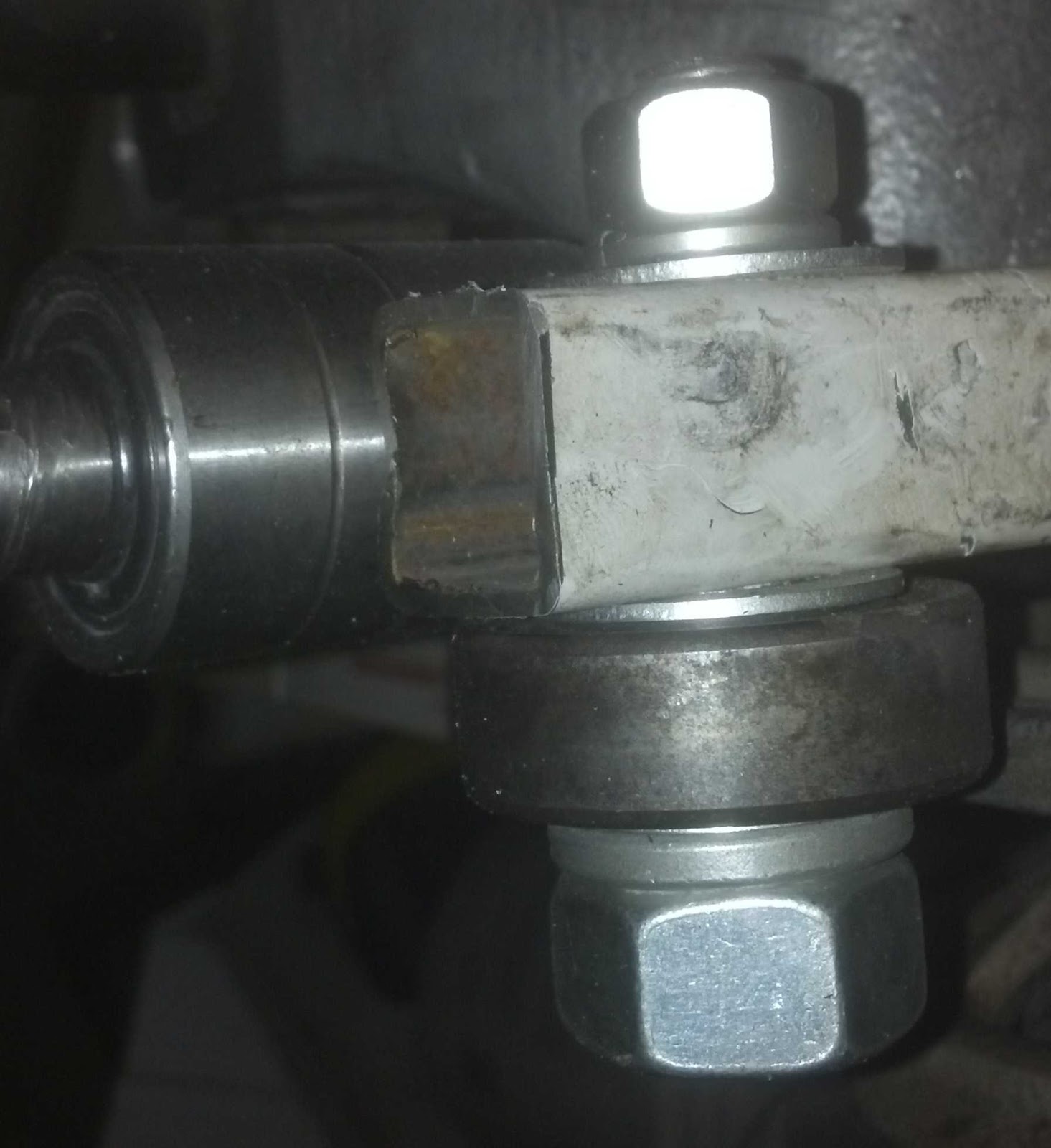
Since I have a long shaft, I can accomplish tracking adjustments by moving one end of the shaft while the other end is stationary. That's what the chain in the center of the picture does. Normally it turns both threaded rods at the same time to adjust the blade tension.
By loosening the thumb screw behind the conduit 'handle' on the right, we can keep the rear threaded rod stationary while the chain turns only the front screw to adjust the tracking. There is a flat plate attached to the front of the mill head that the front threaded rod moves and the rear alignment is handled by a scrap of the same 2 1/2 x 2 1/2 box tube running inside a scrap of the 3x3 box tube. Most likely overbuilt to the max, but that's how we tend to fly around here..
You can also see the 5/8 all thread that runs vertically to raise and lower the mill head. We used a coupling nut so we had more threads to bear the load. Trying to align multiple nuts and weld them in place will NOT work, the heat will make them move just enough that they will bind. You can get all thread in lengths up to 6 foot long cheaply..
The wheel hub on this end (the idler) is 100% standard trailer hub, tapered roller 'wheel' bearings, rear seal, grease cover, etc.
Continuing to walk around, here is the front of the mill head:

Still looking at the idler side. you can see how the mill head frame needs to resist the tension of the blade. The Simple Saw design runs a box tube right inline with the wheel axles. Which directly opposes the force that the blade tension puts on the entire mill head. And if you know how much tension it takes to keep a 1/2 wide band on that Rockwell Delta saw tight and running true, you can guess how much tension it takes to keep a blade 3 times that wide at 1 1/2 inches tight and running true..
I wanted to give the saw a larger throat, for a thicker cutting capability. Therefore,we moved the cross piece to the top of the mill head and added 45 degree braces. Have we ever used the full cutting depth of this saw ?? NO (not yet) , but it certainly gives a nice clear view of where the blade is and what its doing..
The blade guides on both sides of the saw are the same and they are a set of ball bearings,
The 'hold down' bearings are some odd ball 2 inch long bearings premounted on stub shafts that I found at Surplus Center, and they no long have them.. Many people just put double or triple bearings on a common shaft.
The "backup bearing" is a standard flat race bearing from a lawn mower hub if I recall. I made cams - offset shafts by turning a 3/4 shaft that fits the bearing ID, down to 5/8, which is what runs up through that box tubing. If you loosen the top 5/8 nut you can rotate the shaft and adjust how close the bearing is to the back of the blade. The shafts look like this:

Cams like these are NOT that hard to make on a lathe. You just add a spacer between one of the three jaws of the chuck equal to the offset you want and tighten it up and turn the shaft to size..
The 'blade guides' on the idler side of the mill head can be adjusted in and out to widen or narrow the cutting throat, and they can also be adjusted up and down. The driven side guides can only be adjusted up and down. Those adjustments let you square the blade to the saw's travel and also allows you to 'lift' the blade off the tires as it cuts to keep the blade more stable.
Walking around some more we get to the drive side of the mill:

We used (re used) an 1 1/4 inch shaft on standard 'pillow block' ball bearings with a 10 inch pulley on the end as a final - main drive shaft, the shaft used to be in a JI Case combine..
The end that drives the wheel has 2 sprocket hubs on it that were turned down on the lathe to fit inside the wheel hub. We drilled and tapped holes from the outside of the wheel's hub into the 'sprocket' hubs and bolted it all together..
I was really concerned that welding the cast iron trailer hub would cause things to crack, so we bolted it together instead.
There is some adjustment possible in the pillow block bearings as well as the shaft that the idler rides on so you can make sure the tires are running plumb, straight, level, etc.
Also once you get this all assembled and working, without a band on the tires, grind - sand down the drive wheel to take the bulges out of it and also to form more of a crown on the tire. With the engine running, put a sanding disc on an angle grinder and go to it.. (A dust mask and goggles MIGHT be handy, just saying.. :-) You should be able to hold the grinder steady enough by hand to accomplish the job.
Then swap tires, put the idler wheel on the driven side of the mill head and do the same process to it.. (your idler hub had better run fairly true, if not you've got other issues you need to attend to.
Each one of these saws and saw builds is unique, Hopefully that explains the choices we made and gives you some ideas to work from.